How to Draw Images in a Plane Mirror
2.2: Images Formed past Airplane Mirrors
- Page ID
- 4492
Learning Objectives
Past the end of this section, you will be able to:
- Depict how an prototype is formed by a plane mirror.
- Distinguish betwixt real and virtual images.
- Find the location and characterize the orientation of an image created by a airplane mirror.
Yous only take to expect as far as the nearest bathroom to find an instance of an image formed by a mirror. Images in a aeroplane mirror are the same size as the object, are located backside the mirror, and are oriented in the aforementioned direction as the object (i.e., "upright").
To understand how this happens, consider Figure \(\PageIndex{one}\). Two rays emerge from point \(P\), strike the mirror, and reflect into the observer's center. Note that we utilize the law of reflection to construct the reflected rays. If the reflected rays are extended astern behind the mirror (run into dashed lines), they seem to originate from point \(Q\). This is where the prototype of signal \(P\) is located. If nosotros repeat this procedure for point \(P′P′\), we obtain its paradigm at betoken \(Q′\). You should convince yourself past using basic geometry that the epitome height (the altitude from \(Q\) to \(Q′\)) is the same equally the object height (the distance from \(P\) to \(P′\)). By forming images of all points of the object, we obtain an upright prototype of the object behind the mirror.
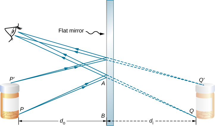
Notice that the reflected rays appear to the observer to come directly from the image behind the mirror. In reality, these rays come up from the points on the mirror where they are reflected. The image behind the mirror is called a virtual image because it cannot be projected onto a screen—the rays only appear to originate from a mutual point backside the mirror. If yous walk behind the mirror, you cannot come across the image, considering the rays do non become there. Nevertheless, in front of the mirror, the rays behave exactly equally if they come up from behind the mirror, and so that is where the virtual paradigm is located.
Later in this affiliate, we talk over real images; a real epitome can be projected onto a screen considering the rays physically go through the image. You tin can certainly meet both real and virtual images. The divergence is that a virtual image cannot be projected onto a screen, whereas a existent image can.
Locating an Image in a Airplane Mirror
The police force of reflection tells u.s.a. that the angle of incidence is the same as the bending of reflection. Applying this to triangles \(PAB\) and \(QAB\) in Effigy \(\PageIndex{1}\) and using basic geometry shows that they are congruent triangles. This means that the distance \(Pb\) from the object to the mirror is the same as the distance \(BQ\) from the mirror to the image. The object distance (denoted \(d_o\)) is the distance from the mirror to the object (or, more generally, from the heart of the optical element that creates its image). Similarly, the image altitude (denoted \(d_i\)) is the distance from the mirror to the prototype (or, more more often than not, from the center of the optical chemical element that creates it). If we measure distances from the mirror, and so the object and epitome are in opposite directions, so for a plane mirror, the object and image distances should have the contrary signs:
\[d_o=−d_i.\]
An extended object such as the container in Figure \(\PageIndex{one}\) can exist treated as a collection of points, and we tin can employ the method above to locate the image of each point on the extended object, thus forming the extended image.
Multiple Images
If an object is situated in front of two mirrors, you may meet images in both mirrors. In addition, the paradigm in the first mirror may deed as an object for the 2d mirror, so the second mirror may form an epitome of the image. If the mirrors are placed parallel to each other and the object is placed at a bespeak other than the midpoint between them, then this process of image-of-an-prototype continues without finish, as you may have noticed when standing in a hallway with mirrors on each side. This is shown in Effigy \(\PageIndex{two}\), which shows 3 images produced past the blueish object. Notice that each reflection reverses front and back, just like pulling a right-manus glove inside out produces a left-hand glove (this is why a reflection of your right hand is a left hand). Thus, the fronts and backs of images i and 2 are both inverted with respect to the object, and the forepart and dorsum of image 3 is inverted with respect to image 2, which is the object for image 3.
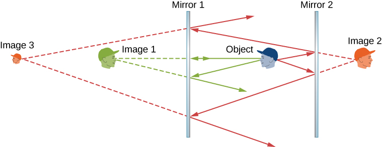
You may have noticed that image 3 is smaller than the object, whereas images 1 and 2 are the same size as the object. The ratio of the image height with respect to the object height is called magnification. More than will exist said about magnification in the next department.
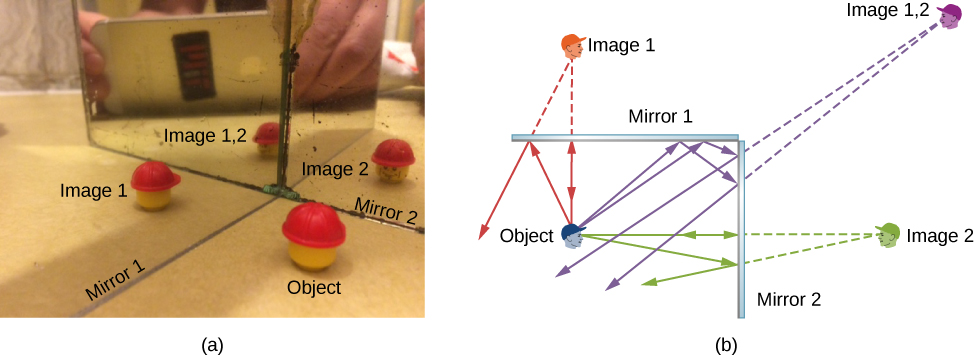
Infinite reflections may terminate. For instance, two mirrors at right angles grade three images, as shown in Effigy \(\PageIndex{3a}\). Images 1 and 2 event from rays that reflect from simply a single mirror, but image 1,2 is formed by rays that reflect from both mirrors. This is shown in the ray-tracing diagram in (\PageIndex{3b}\). To notice image ane,2, you have to await behind the corner of the two mirrors.
Source: https://phys.libretexts.org/Bookshelves/University_Physics/Book%3A_University_Physics_(OpenStax)/University_Physics_III_-_Optics_and_Modern_Physics_(OpenStax)/02%3A_Geometric_Optics_and_Image_Formation/2.02%3A_Images_Formed_by_Plane_Mirrors
0 Response to "How to Draw Images in a Plane Mirror"
Post a Comment